The Router head can be used on the Vision 1624R, 2550, and the VR48 CNC Routers. For this tutorial, a 2550 Vacuum table was used to make a fishing rod holder that requires minimal assembly.
Download Fishing Rod Holder File
For this project, ½” Marine grade HDPE (high density polyethylene) was used as the material. The tools used for this project are a round edge router bit, 1/8” end mill (onsrud 63-712), and the router head. This project can be done on a 2550 non-vac table, using transfer tape and spray adhesive with a spoil board. Make sure that there is a spoil board on the table of the machine, regardless.
**Note** the round edge router bit is for woodworking, while the end mill is for plastic. HDPE is easy to machine, but is recommended to use the appropriate end mills for clean cuts and edges, and make sure the end mills and router bits are sharp. It is also recommended to use the vacuum system; otherwise it will make a mess.

The measurements for the fishing rod holder are: back board=36”x 8”/ shelves=7 3/8”x 3” (a 2’x4’ of marine grade HDPE was used for this tutorial).
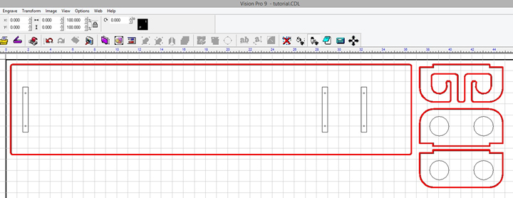
Starting with the software, download the fishing rod holder file and Import into Vision 9 software.
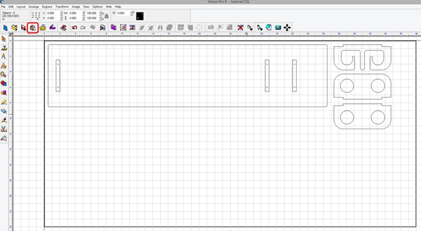
It is a good idea to measure the thickness of the material because even though it is supposed to be ½” does not mean it actually is, however the material for this tutorial was actually ½” thick.
To get an accurate computer representation and calculation for the tools in the tool paths, all the tools used need to be in the Tool Library.
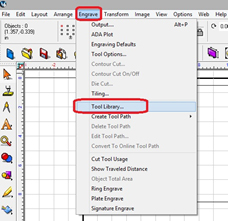
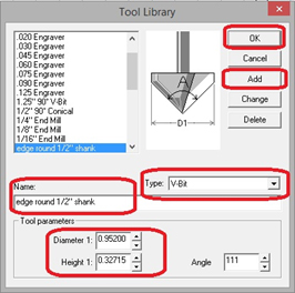
Once in the Tool Library, pick the type of tool, name, input the dimensions, then click Add, then OK. The 1/8” end mill is already in the Tool Library.
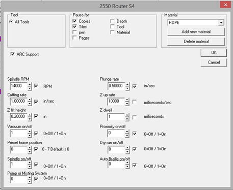
For this tutorial, 2 material selections were used. The first one is the Wood (cutting) in the Tool Options (click on Engrave at the top, then click on Tool Options), this will be used when running the router bit. Another material selection was created to use with the end mill on the HDPE.
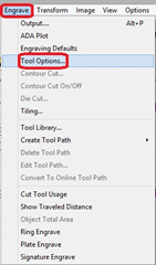
Once in Tool Options, change the settings and name to match the screen here.
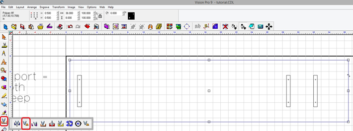
The next step is to apply the tool paths and because this is a somewhat complex project, there will be many different tool paths. Starting with the male tool paths and then on to the drill center, female, and fill tool paths.
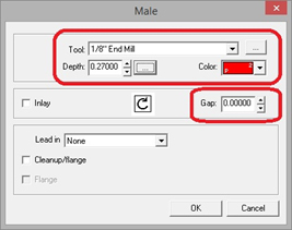
Start with the cutout tool path by selecting the outer line of the back board, selecting the Male Tool Path, then pick 1/8” end mill, depth .52, 2 passes, red (p2), 0 gap, OK.
Repeat the last step with all three shelves.
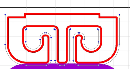
Next step is to apply the male tool path for rounding the top edges. When using a router bit like this, how far the top edges will be rounded are taken into consideration (adding depth for a more rounded edge, adjusting the gap, etc.).
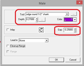
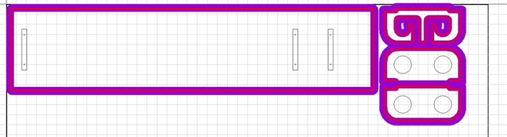
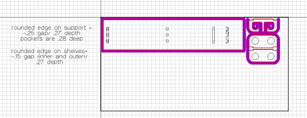
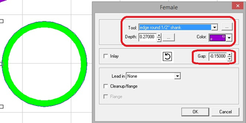
Select the outer edge line of the back board (just like the previous steps), be sure not to select the tool path-the outer edge line will be at the inside edge of the tool path. Apply a Male Tool Path, choosing the router bit for the rounded edges, make the depth .27, 2 passes, purple (p13), -.25 gap, OK.
**Note** You probably won’t have this same router bit, the depth and gap will likely need to be different, it is recommended that testing be done on a scrap piece to see what depth and gap will work best (several tests were run to determine depth and gap for this router bit).
Repeat the last step for the 3 shelves but change the gap to -.15. The tool paths are being layered and show through when done this way.
Since the back of the shelves do not need the top edges rounded, the tool path will need to be edited (tool paths can be node edited). To node edit a tool path, select the tool path (which is always the center of the color), then double left click on the tool path line, this will bring up the nodes.
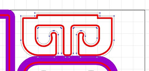
Left click on a node, then hold down the right click and slide the cursor over the bottom center symbol and let go of the mouse button, this breaks the line.
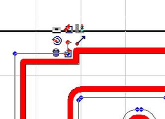
With the line broken, the unnecessary nodes can now be deleted to have the tool path go around the front, sides, but not the back of each shelf. Left click on each node to be deleted and push the delete key, afterwards, Select Tools to get out of node editing (left menu) or Apply on the top menu to do the same thing.
Repeat the last step for the two other shelves.
**Note** It is highly recommended that when making templates or even doing one offs, that notes are used so the guess work and confusion are taken out of the work. There is plenty of space around the outside of the Plate to put notes and only what is inside of the Plate can be run by the machine.
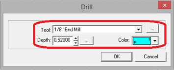
Next step is to apply the Drill Center Tool Paths. Since the screw holes are only 1/8” and our end mill is 1/8” the female tool path will not work. Select the screw holes, and then select Drill Center Tool Path.
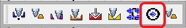
Choose the 1/8” end mill, depth of .52, 2 passes, blue (p5), OK.
Next step is to apply the Female Tool Paths to cut through. Select the circles in the second shelf down, select Female Tool Path, choose the 1/8” end mill, depth of .52, green (p6), 2 passes, 0 gap, OK.
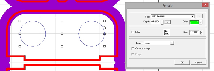
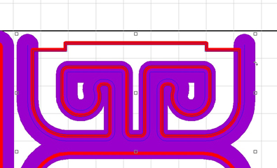
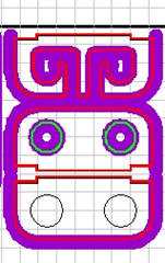
Next step is to apply the rounded edge Female Tool Path. Select the circles again but not the tool path (the circle line will be at the outside edge of the tool path), select female tool path, choose the router bit, depth of .27, 2 passes, purple (p13), -.15 gap, OK.
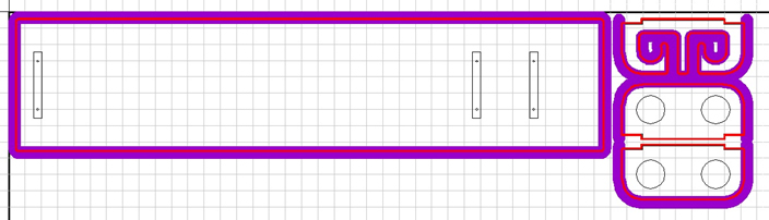
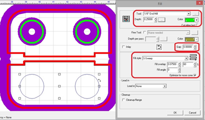
Next step is to apply a Fill Tool Path for the pockets. Select the circles in the last shelf, select Fill Tool Path, 1/8” end mill, depth of .25, 1 pass, green (p6), 0 gap, fill style is s-sweep, fill overlap at least 60% (higher percentage will make pockets smoother), 0 fill angle, OK.
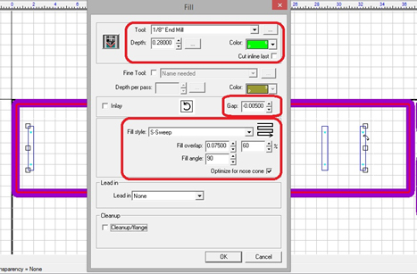
Next, select the pockets (long rectangles) on the back board, choose Fill Tool Path, 1/8” end mill, depth of .28, 2 passes, green (p6), -.005 gap, s-sweep, 60% overlap, fill angle of 90, OK.
**Note** If the material you are using is not .5” thick, the width of the rectangles for the pockets can be adjusted to the proper size (just remember to align everything back up).
Now that the job is set up in the software, next is to set up the machine. Make sure the router head is attached and the proper size router collet is inserted. The first tool used for this job is the router bit for the rounded edges.
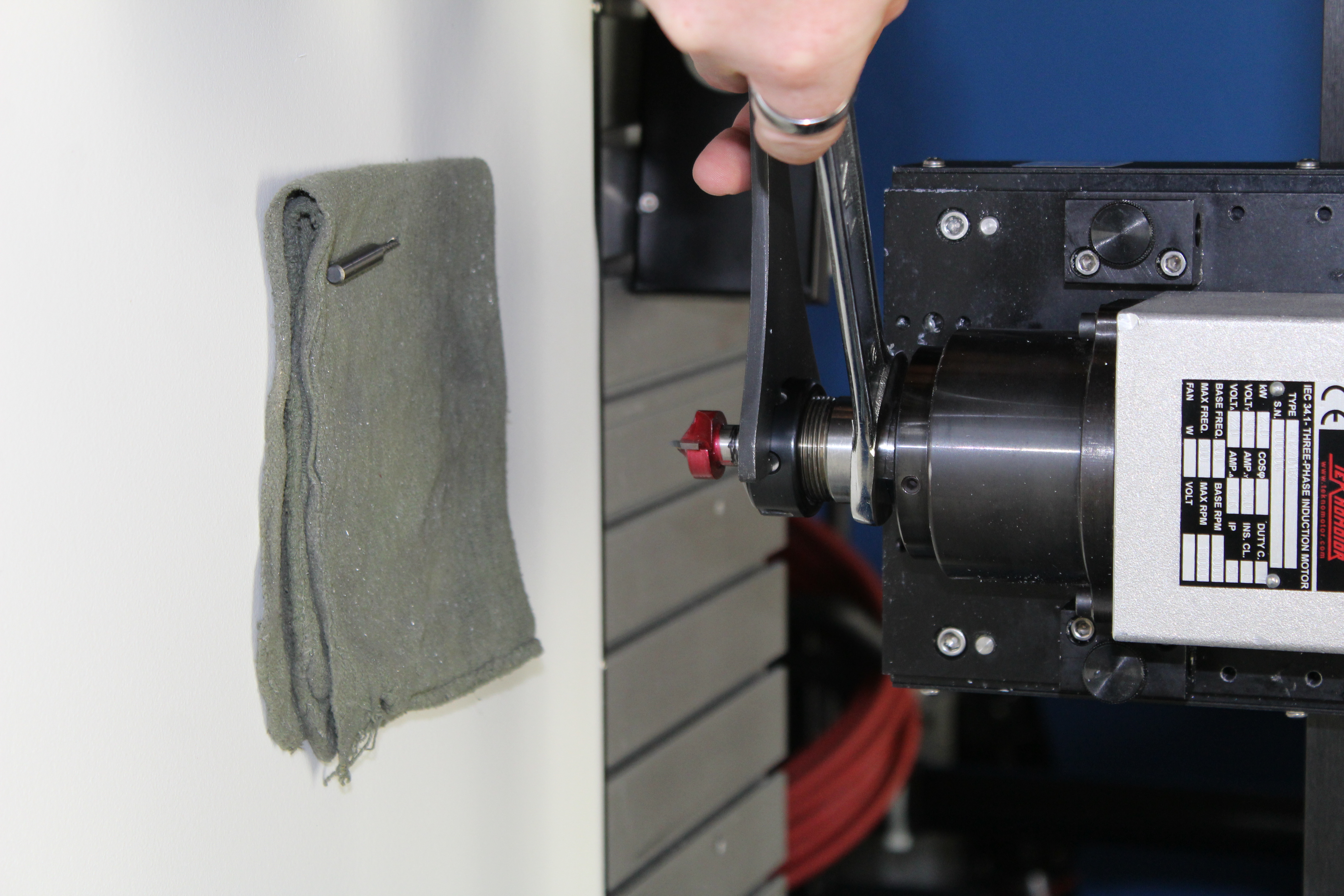
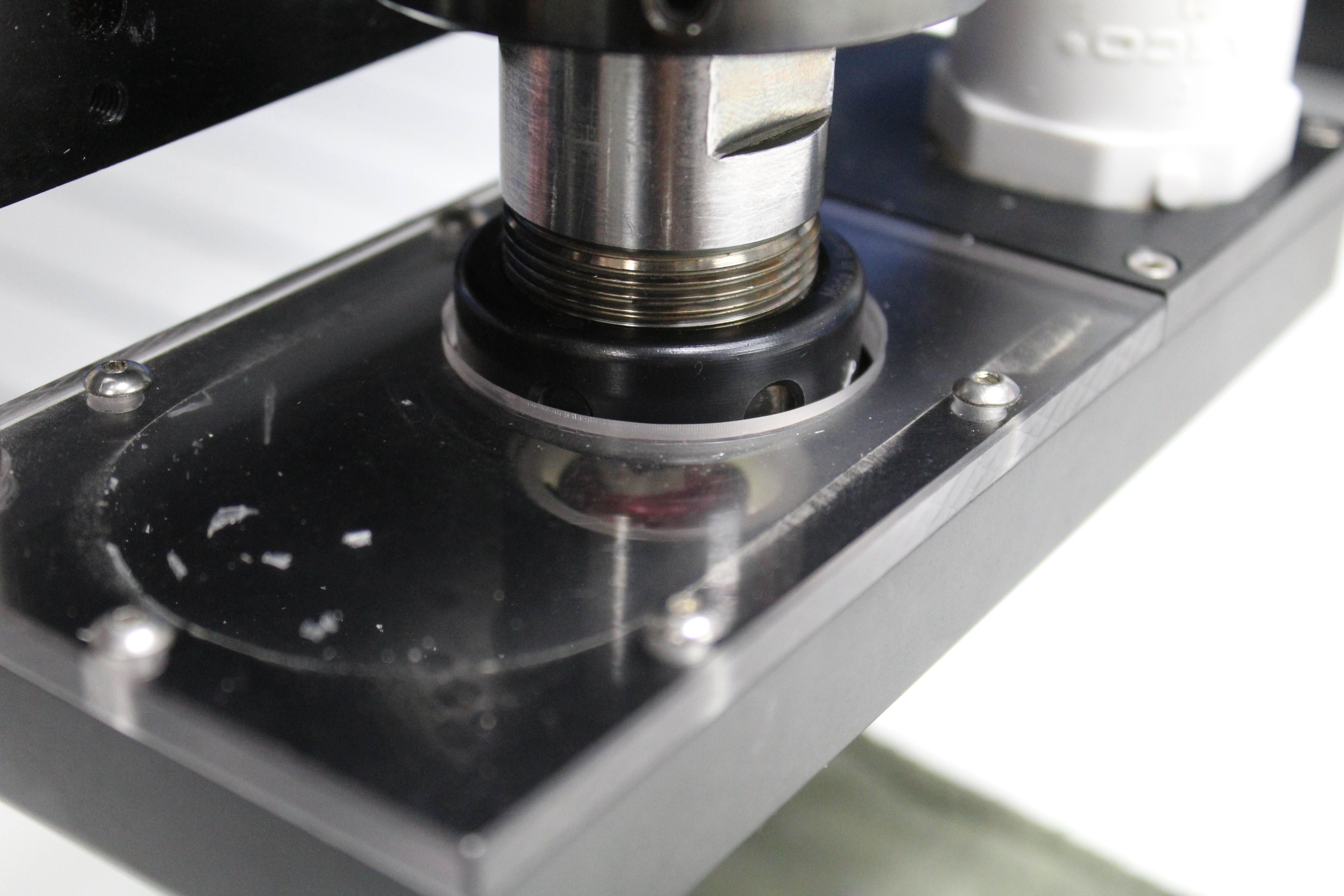
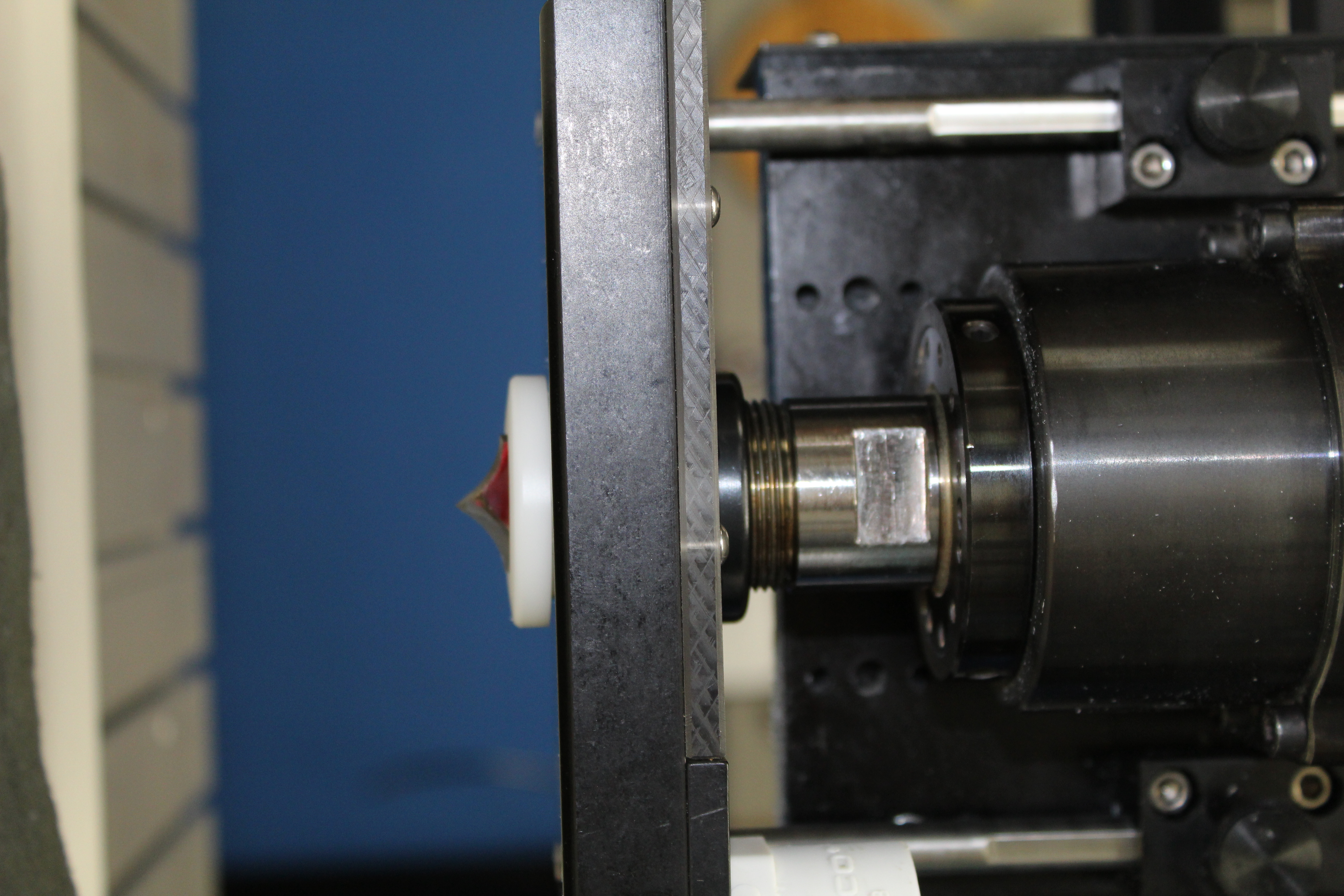
**Tip** It is recommended to put a cloth rag under the router when installing and taking out router bits and end mills as a safety cushion. Also, if using the dust collection head, make sure to leave room between the bottom of the white collar and the bottom of the router shaft.
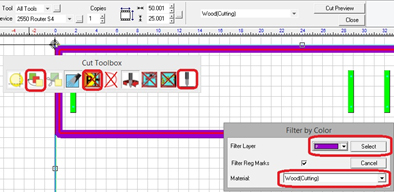
Once the router bit (and dust collection head if used) is installed, make sure the material is securely in place, make sure the home is set in the proper location, and set the surface. Now the job can be sent to the machine to run. For this tutorial, the cut by color method is being used.
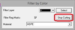
Select the entire job, Engrave (on the left side), select Filter by Color, make sure the Wood (cutting) for material is selected, make sure the Prox Sensor is off, choose the purple, Select, then click on Engrave.
Once the purple tool path is run, change the router bit to the 1/8” end mill (make sure there is enough of the end mill sticking out to cut through the material), and set the surface again. Go back into the software and choose green as the color, change the material selection to HDPE, and then Select. Run the blue, and then the red will be last. Once the red has run, select the Stop Cutting.
That is the end of the job, now the shelves should fit snugly into the back board and be attached by screws from the backside (counter sinking the holes is recommended). Now you have a complete fishing rod holder.

Vision 2550 CNC Router
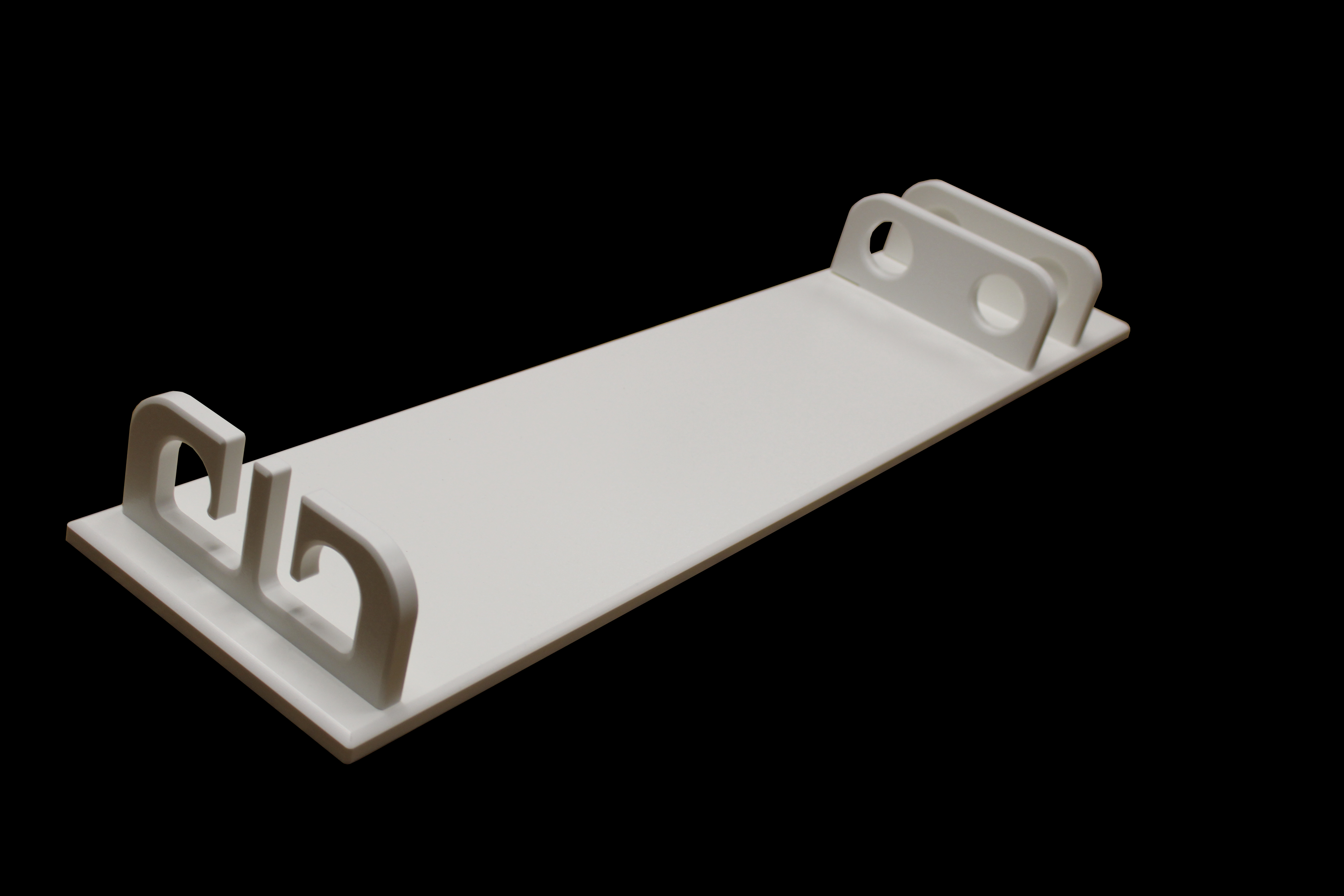
The finished Fishing Rod Holder made with Marine Grade HDPE
Download Fishing Rod Holder File
Contact Vision Engraving & Routing Systems today to learn more about CNC Routers, get a price quote, request a free online demo, or call 1-888-637-1737.