Rotary engravers are the perfect choice for creating ADA signs because they provide the beveled cut required for the raised elements within the sign and provide a consistent size and depth of hole for ADA Raster Braille. Since public buildings are required by law to have ADA signs (including raised lettering and Braille), supplying them to customers can be highly lucrative. The cost of materials can be as low as $0.07 per square inch. Some shops stay away from creating ADA signs because they are unfamiliar with the government rules and regulations and fear that these signs are difficult to create. However, ADA signs are not hard to make, especially with an Automatic Raster Braille attachment and Vision’s ADA Assistant Software, which assists with all spacing, fonts, and pictograms used in these signs. The software automatically alerts the user if there are errors in letter height, sizing, spacing, or placement of any of the elements so that there is no guesswork in whether or not the sign is compliant.
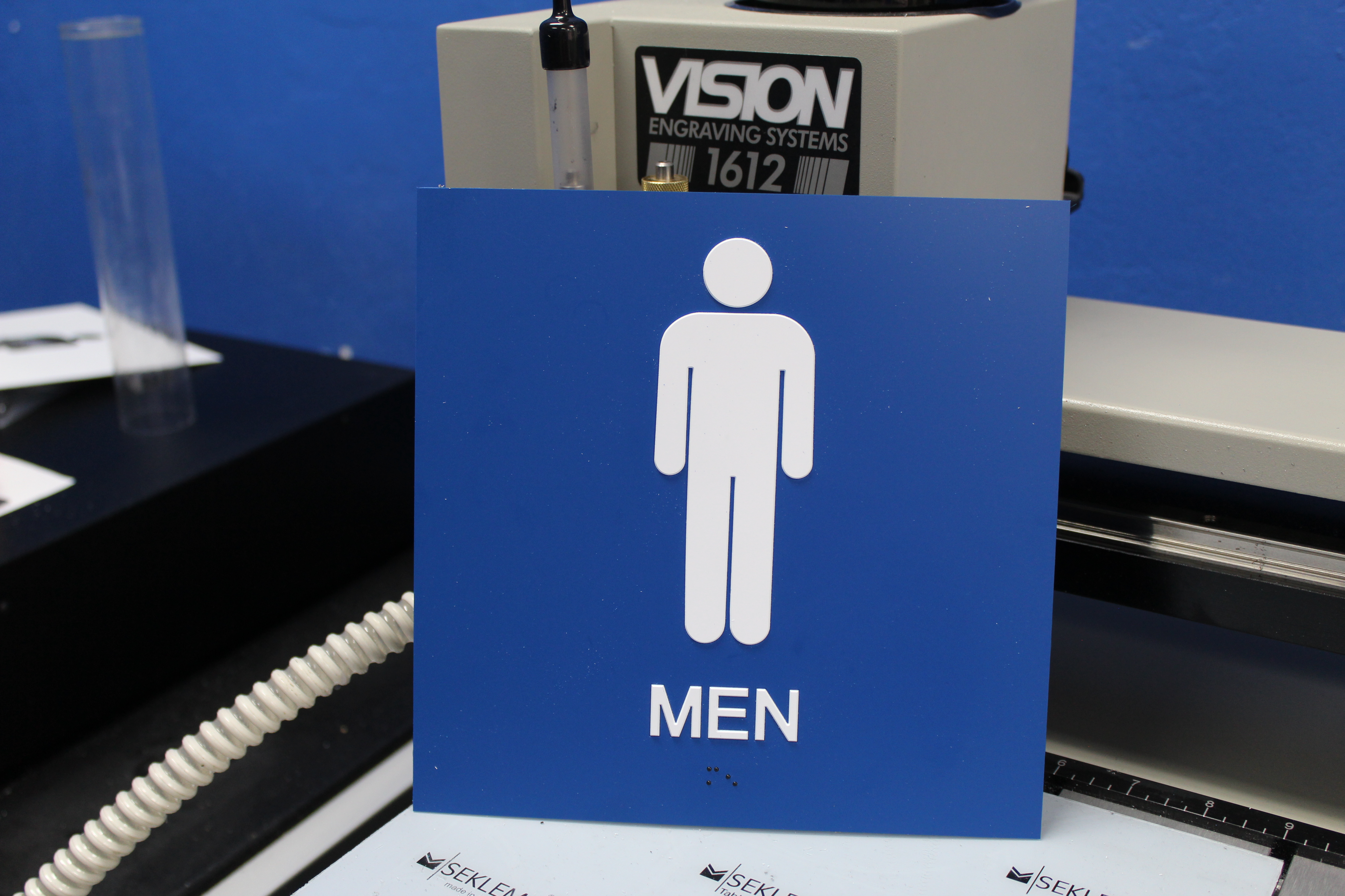
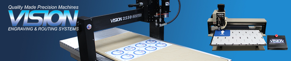
In this tutorial, we’re going to show you how to make a basic 8” by 8” ADA-compliant sign from start to finish. ADA signs can be created using any Vision engraver, but the automatic Raster Braille inserter can only be used on the 16 Series and larger machines. For this project, we’re using our 1612 Engraver and Series 4 Controller, the automatic raster Braille inserter to insert the Braille rasters, and our Vision Pro 9 Software. We are using two sheets of engraving plastic – a white 1/32” sheet with an adhesive backing for the raised elements, and a 1/16” sheet in a contrasting color for the background. Both sheets are precut to 8”x8”. We are also using clear Braille rasters for the Braille text and a MultiMat to hold the plastic material onto the table. To cut out the raised elements we will use a flex cutter with a small tip of .020”. To drill the holes for the Braille rasters we will use an ADA Braille drill cutter.
Step 1 – Machine and tool setup
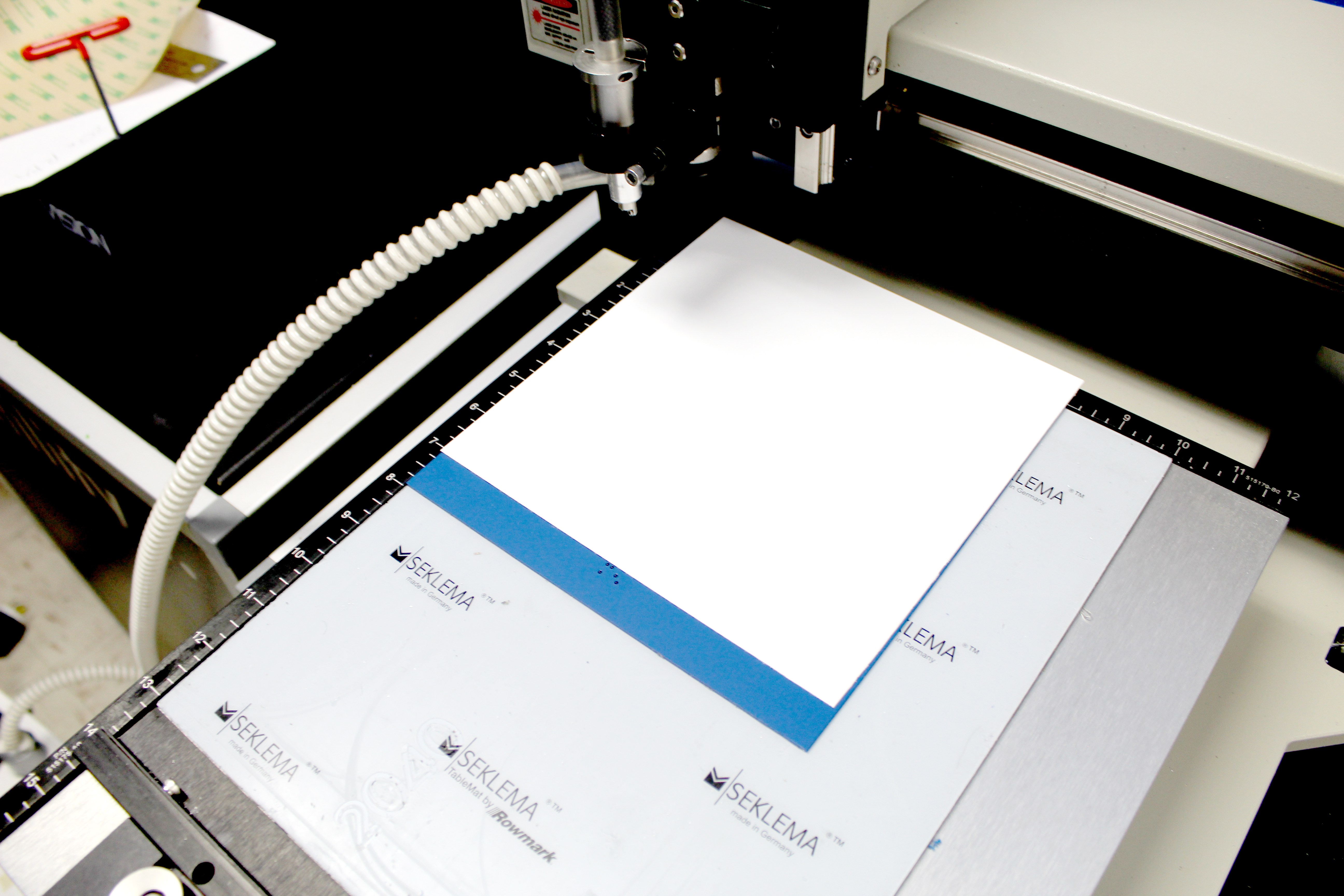
To start, power on the Series 4 Controller. On the pendant, press the “Go To Home” button to initialize the system. Place the 1/16” plastic material for the background onto the table in the top left corner. Use the arrows on the Controller to move the spindle somewhere out over the material.
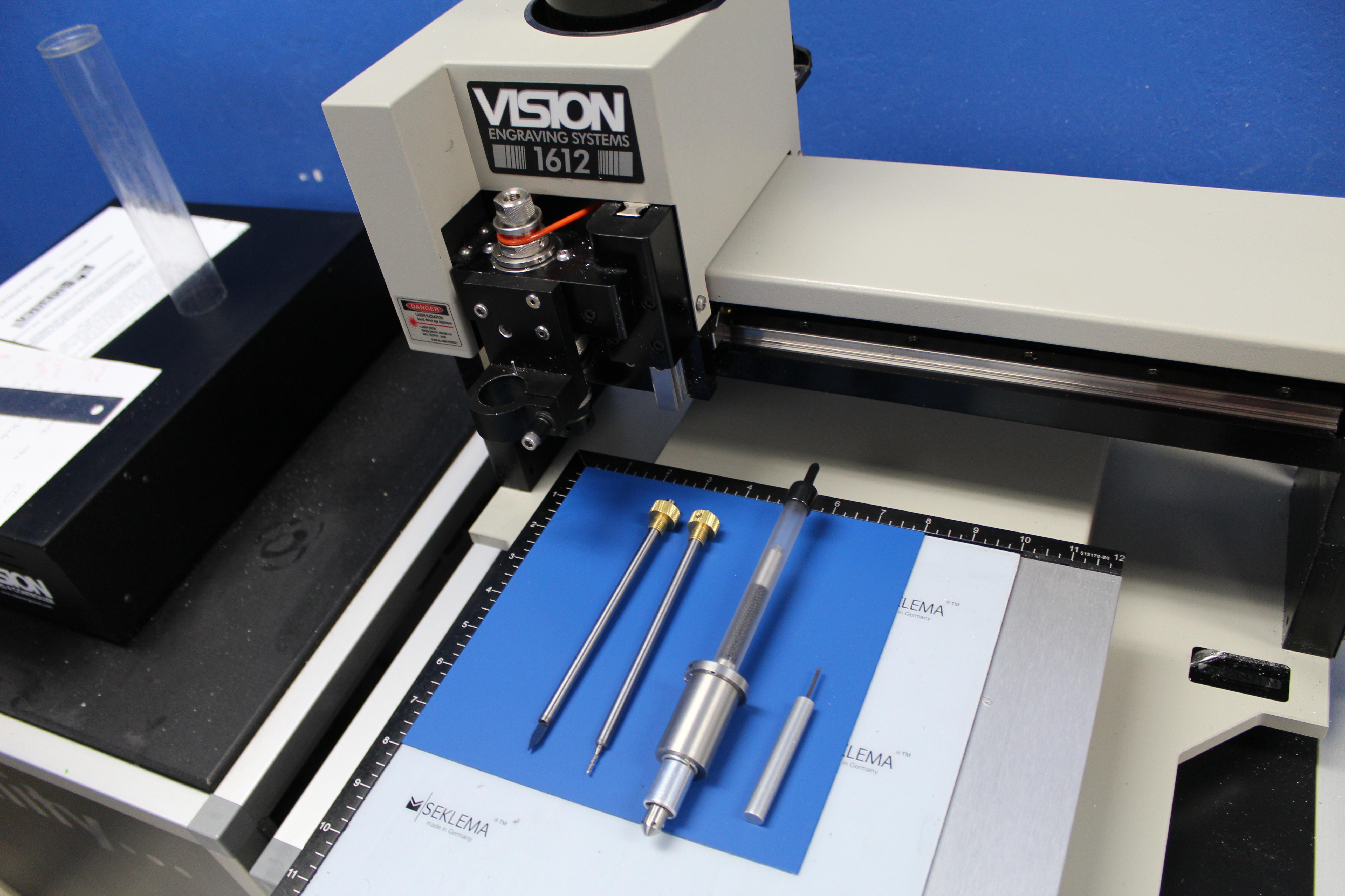
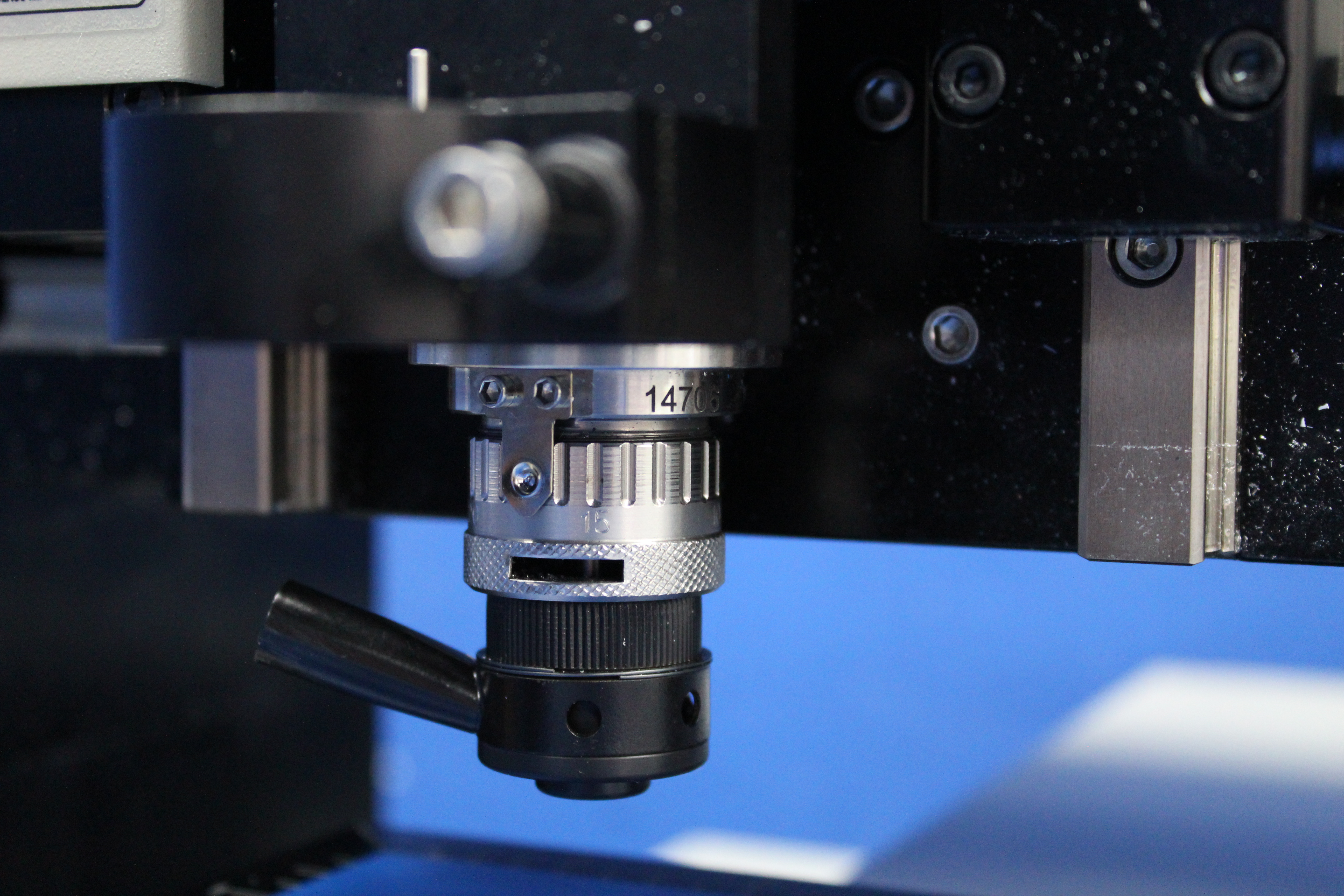
We can now zero the cutters, or set the cutters flush with the bottom of the nosecone, so we can use the micrometer to set the engraving depth in our job. Each click of the micrometer is .001” of depth and each complete revolution is .025” of depth. Back off the micrometer at least 2 revolutions from the top to allow a depth of up to .050”. Start with the micrometer at “0” for reference.
We’ll start by zeroing the Braille drill. Loosen the set screw on the cutter knob and move the cutter up about 2”. Tighten the set screw to hold it there. Put the cutter into the spindle by threading it counter-clockwise. Now lower the spindle until the nose cone touches the material and the tension spring compresses slightly. Loosen the cutter set screw while holding onto the cutter. Gently lower the tool until it makes contact with the material. Tighten the set screw. This sets the cutter flush with the bottom of the nose cone. Use the Z Up jog button to raise the spindle off the material. Now remove this cutter from the spindle.
Note: The holes for the Braille rasters are drilled at .042” and the raised elements are cut at .035”. Therefore, the raised elements are cut at .007” less depth. If we rotate the micrometer 7 clicks before we zero the flex cutter, it will be set at .007” less depth than the Braille drill. This means we only have to set the micrometer once for the whole job. When we dial 42 clicks to the right, or .042”, for the Braille drill, the flex cutter will be at .035”. We call this method “indexing” cutters. With a little work setting up the tooling this indexing cutters will greatly simply the production process.
We will now zero the flex cutter. Rotate the micrometer 7 clicks to the right. The micrometer should be set to 7. Repeat the steps for zeroing the cutter to set the flex cutter flush with the bottom of the nose cone. Use the Z Up jog button to raise the spindle off the material. Now remove this cutter from the spindle.
You can now dial the micrometer to 42 clicks past zero and leave it there for the whole job. Since there are 25 clicks around the micrometer the final setting should be at 17 or 1 full revolution plus 17 clicks (25+17=42).
The cutters are now indexed. The Braille drill is set to .042” for drilling the raster holes and the flex cutter is set to .035”
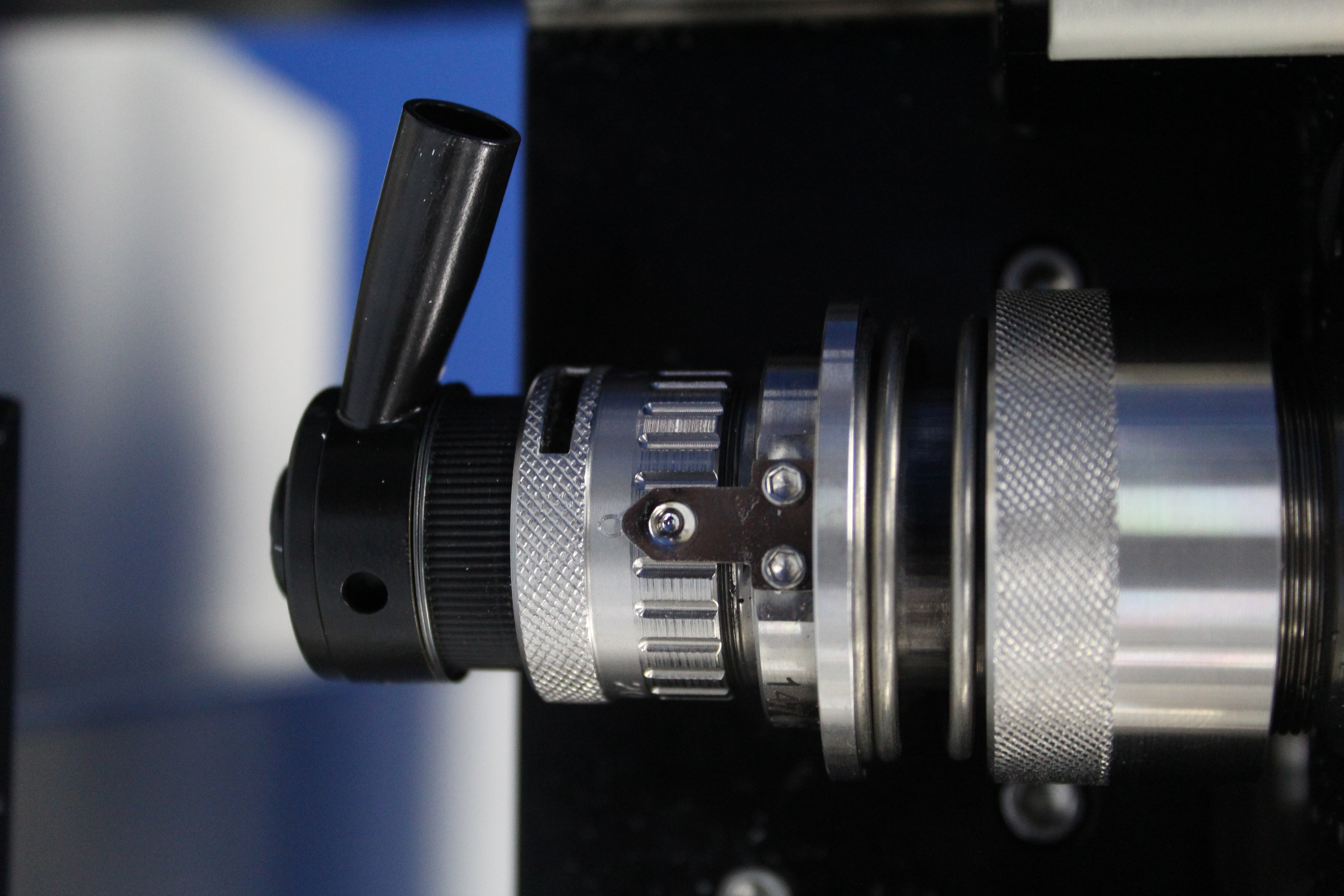
We set the surface for the Braille pen attachment to establish the amount of pressure used to insert the Braille rasters. Use the arrows on the pendant to again move the spindle somewhere out over the material. Insert the Braille pen into the bracket, and locate it correctly by rotating it until the pin on the bracket enters the hole in the ring. Do not tighten the nut that locks the pen in place at this time. Lower the spindle until the Braille pen rises above the adapter and the ring is almost flush with the top of the locating pin.
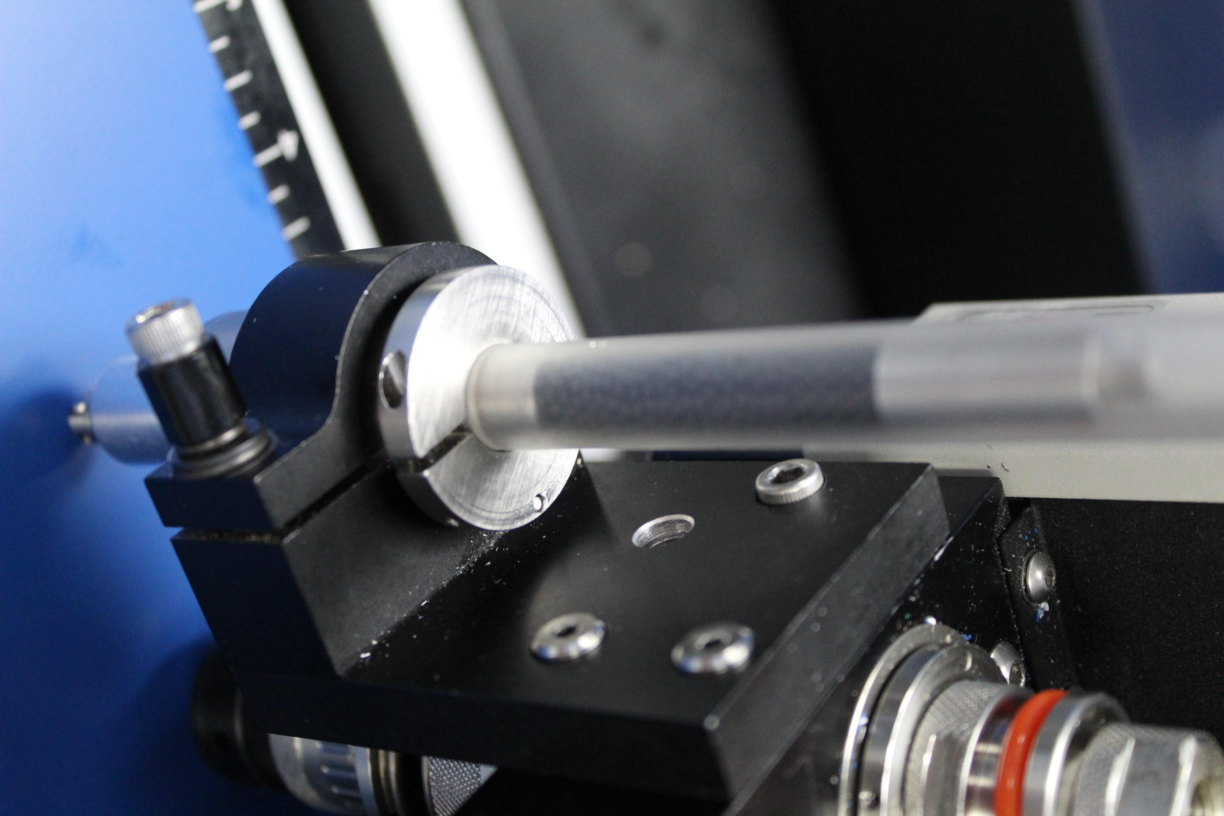
This is the recommend pressure for this application. The pressure can be set heavier or lighter based on the substrate. On the pendant, press the “Set Surface” button, and press “Enter” to set. The spindle will lift slightly, indicating that the surface has been set. Lift the pen high out of the way and lock in place by tightening the nut on the bracket. Press the “Go to Home” button to send the spindle back to the home position.
Step 2 – Software setup
Several ADA-compliant templates are included with the software. They can be modified to create custom ADA-compliant signs. For this project, we will open one of the ADA-compliant templates.
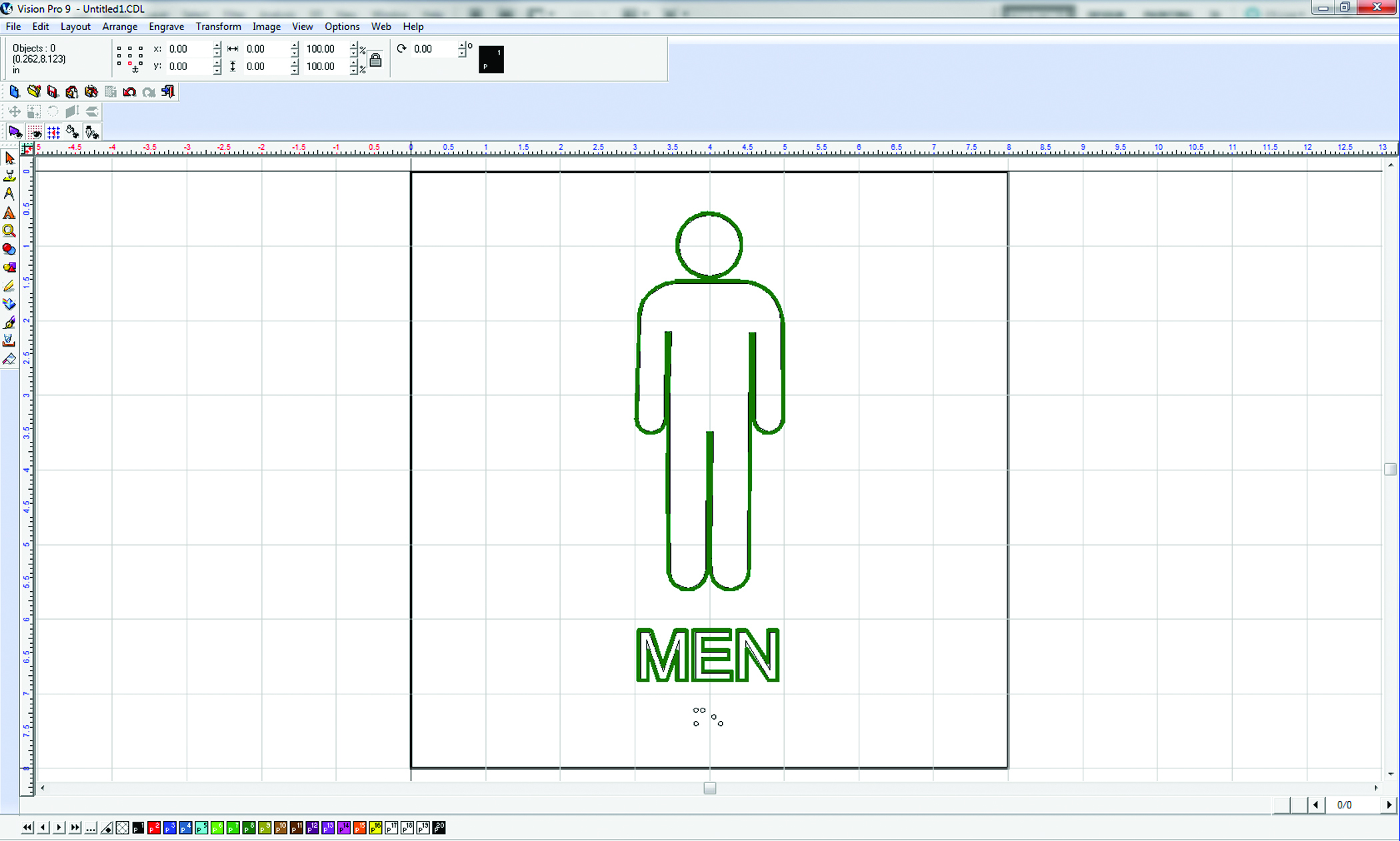
We need to create toolpaths to cut the raised elements and drill the holes for the Braille rasters. Press “F3” to select all objects in the job. To create a toolpath, select “Engrave” from the menu at the top of the screen. Next select “Create Toolpath” and choose the “ADA profile” option. Select the cutting tool we are using to cut the raised elements in the sign — in this example, the .020” engraver. Click on the 3-dot box next to the depth to access the “Engrave Parameters”. Set the depth of the tool path to .035” at 1 pass. Now the software can automatically calculate where to place the toolpath so the raised elements will be ADA-compliant. The job is now ready to send to the machine.
Step 3 – Execution
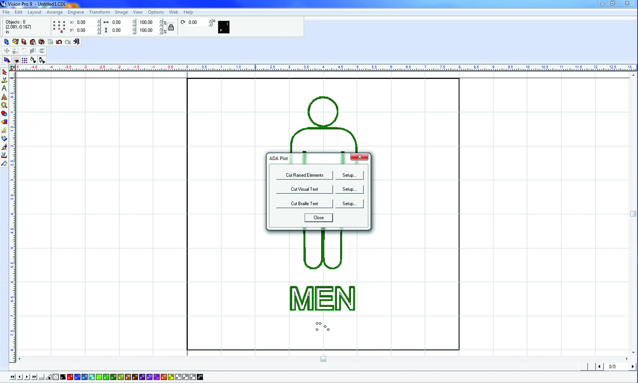
In the software, choose “Engrave” from the menu at the top of the screen and select “ADA Plot”. Choose the “Cut Braille Text” to bring up the job preview and the Cut Toolbox.
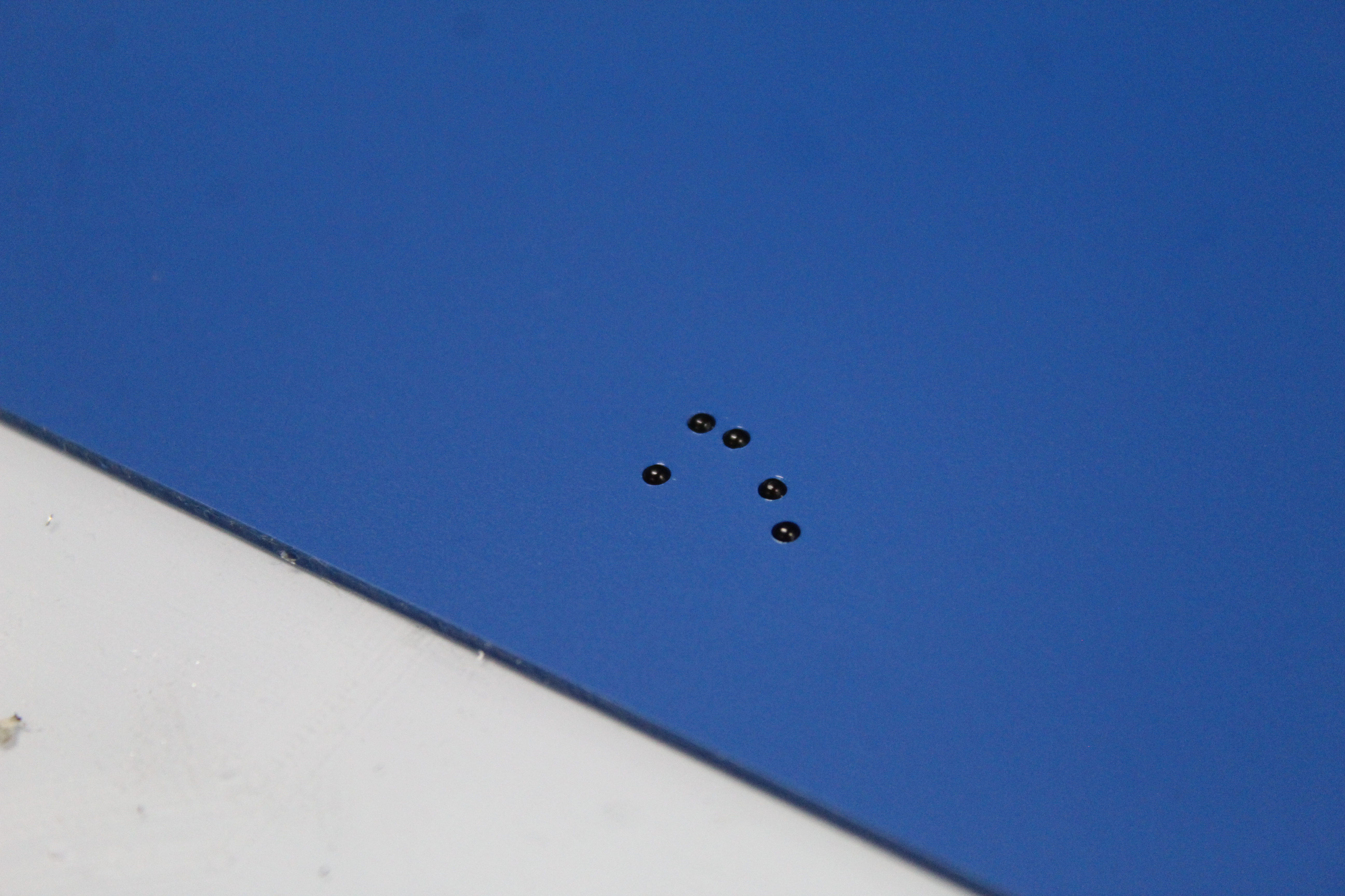
In the Cut Toolbox, the Vacuum, Proximity Sensor (or Prox), Spindle, and Braille icons should be on. Choose the last icon on the right side of the Cut Toolbox – the Engrave icon – to send the job to the machine. You should see a job displayed on the pendant. Push the “Start” button to begin the drilling of the Braille holes.

When the holes are finished the pendant will ask you to lower the Braille inserter. Loosen the nut on the bracket to lower the pen into place, making sure the alignment pin on the bracket is in through proper hole on the inserter. Tighten the nut again to lock it there. Press “Start” to insert the Braille rasters into the holes. If you do not have an automatic inserter, you can insert the beads manually using the Raster Braille Pen. When the rasters are all inserted, pendant will prompt you to raise the Braille inserter. Lift the pen high out of the way and lock in place by tightening the nut on the bracket. Press start to complete the job.
Attach the 1/32” material with adhesive to your background material. We can offset the material slightly to make the removal easier after we cut out the raised elements.
In the software, choose “Engrave” from the menu at the top of the screen and select “ADA Plot”. Choose the “Cut Raised Elements” to bring up the job preview and the Cut Toolbox. In the Cut Toolbox, the Vacuum, Proximity Sensor (or Prox), and the Spindle should be on. Choose the last icon on the right side of the Cut Toolbox – the Engrave icon – to send the job to the machine. You should see a job displayed on the pendant. Push the “Start” button to begin the cutting of the raised elements.
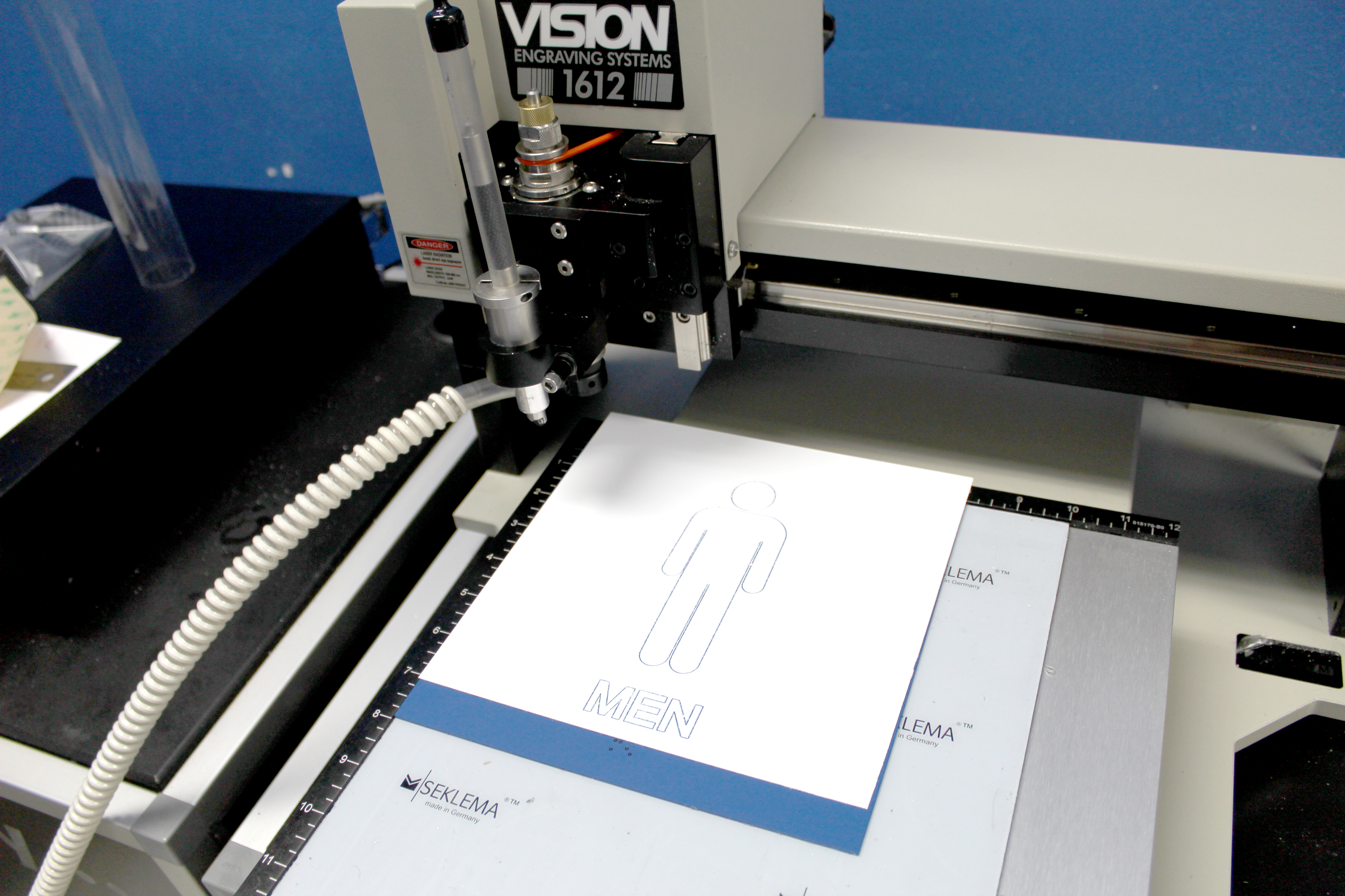
When the cutting is done, take a brush and brush away any debris that is stuck to the sign before removing the excess material. Now pull off the excess, leaving the letters and images. If your sign has letters that require additional material removal, use a tool such as a flat-tip screwdriver for weeding.

With this, you have completed an 8” by 8” ADA- compliant sign.