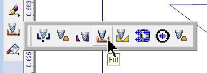
When it is desirable to engrave the inside of an object, the Fill tool is used to create a tool path pattern that covers the area to be engraved. To begin, draw any object in the Vision engraving & routing software and select it (Vision Expert version is used here), then select the Fill tool from the Tool Path Tools icon of the left toolbar.
The Fill window will appear. In this window, the user can change many parameters which will determine how the fill will be processed as well as the final appearance of the engraved item.
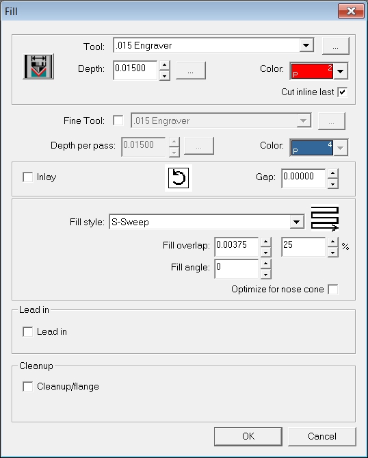
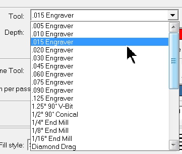
Begin by selecting the primary tool (cutter) being used to engrave the item from the Tool drop down list.
Then, select the depth the item is to be engraved. Even though we may not be using the Set Surface procedure (we can use the Proximity Sensor), the depth must be set here. Depending on the tool being used, the depth may determine the width of each engraved line. In the case of an engraving tool, which has a V shaped tip, more depth will produce a wider engraved line. The Vision software compensates for the wider line by adjusting the number of tool paths as well as how far apart they are separated.
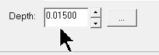
After typing in the depth, select the icon to the right of the depth field.

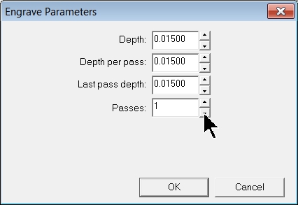
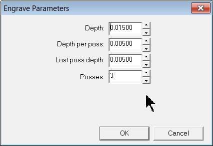
The Engrave Parameters window will appear. This is where the number of passes will be set. If using the proximity sensor, set the number of passes to 1 by clicking on the down arrow to the right of the passes field as shown here. Then select OK to close this window.
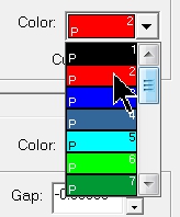
Choose a different color than the color of the object drawn on your screen for the tool path being created. This allows selection of the tool path only when sending the job to the machine.
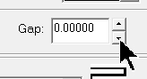
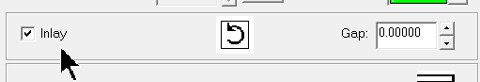
The gap setting can be used to “undershoot” or “overshoot” the outside edges of an object, depending on whether a positive or a negative gap is set.
The Inlay option is used with the Gap setting for applications where a pocket is to be engraved into an item large enough to allow a mating item to be inlayed inside the engraved area. This feature will be discussed in a future Quick Tip.
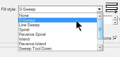
Choose the fill style from the drop down list. It is recommended that users experiment with these different fill styles, as they not only affect the appearance of the engraved item, but also the total processing time. Try using the Spiral fill on mostly round objects or text as an option to speed up engraving time.
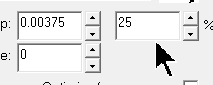
The overlap is the percentage each pass of the cutting tool will overlap the previous pass. Depending on the material, the tool and the desired surface finish of the engraved area, the overlap can be adjusted from 5% to as much as 75%. The overlap and percentage of overlap fields are linked. The use can either set the overlap in inches, or as a percent.
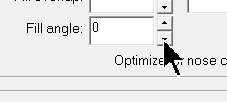
The fill angle can be adjusted on some fill styles. Try using a 30 degree angle and the line sweep fill style with a diamond drag tool for one pass, then use a -30 degree angle for a second pass to create a cross hatch pattern.
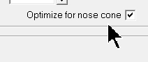
The option to optimize for nose cone can be used when using the proximity sensor. This feature engraves larger areas from the inside out, so the nose cone cannot “fall” into a previously engraved area. This feature is very useful when engraving large simple designs.
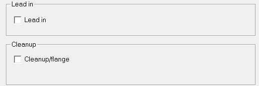
The Lead in and Cleanup/flange are not normally used when creating fills. Leave them unchecked.
Another option is using the Fine Tool to increase detail on intricate designs. This will create a second tool path fill that reaches into the detailed portions of the graphic. The tool used is typically a few sizes smaller than the tool used for the main fill pattern. Use a different color and set the depth to the same amount as the larger tool.
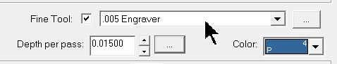
Select the icon to the right of the depth field.
Then, adjust the number of passes depending on the tool being used. Fine tools are more easily broken, so 2 or more passes may be necessary to achieve the desired total depth.
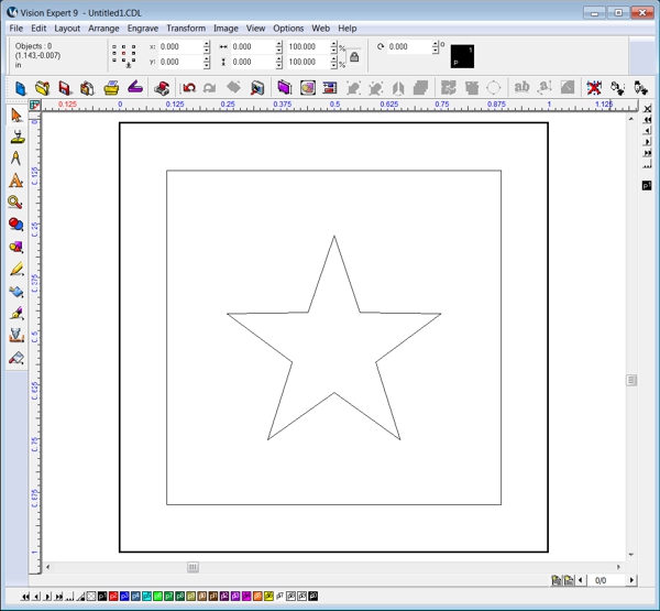
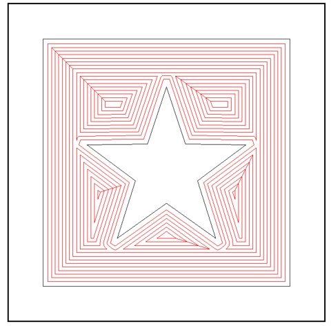
The below objects will be filled using the .015 engraver tool, a depth of .015 inches and using the s-sweep fill style with a 25% overlap.
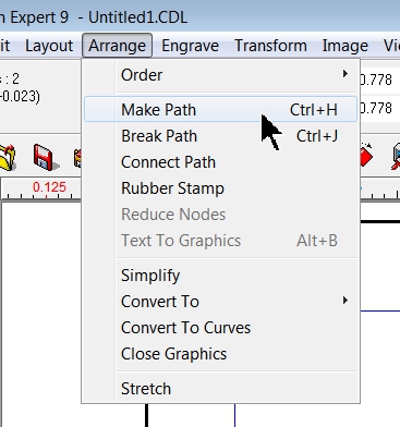
In order to fill the square and not the star, select both objects and select the Arrange – Make Path command from the top menu bar.
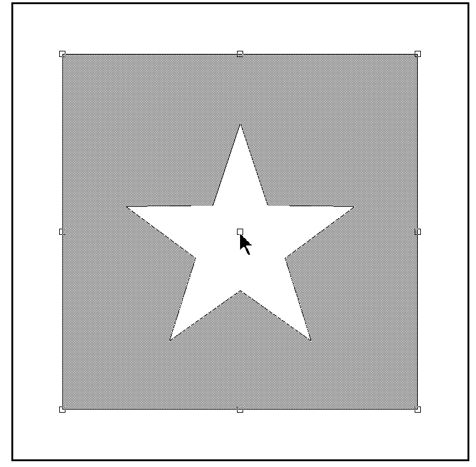
With both objects selected, click and hold down the left mouse button with the mouse pointer over the center node of the selected items. This will display an area (in gray) that depicts where a fill pattern will be applied.
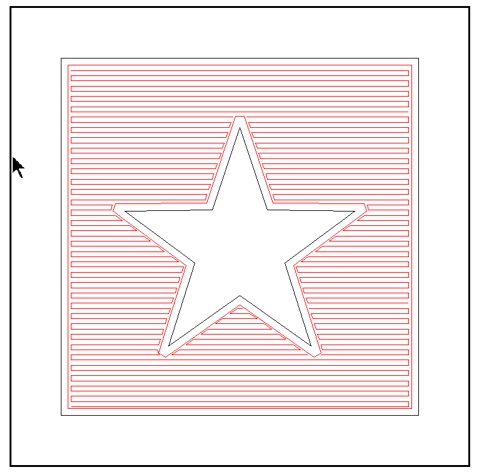
Fill the objects using the Tool Path Tools – Fill tool with the above settings. The fill path will appear as below (click in an open area to deselect all objects). Notice that the red tool path does no touch any of the original object’s lines (in black). The fill path compensated for the width of the cutting tool and adjusted the fill pattern to represent the actual objects when engraving is complete.
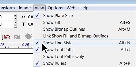
To view a representation of what the actual engrave item will look like, select the View – Show Line Style command (this is a toggle, so after the command turns on, it will have a check mark next to the command in the top menu. To turn off, simply click on the Show Line Style command again).
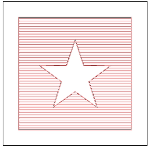
The red area shows what the engraved item will look like using the .015 engraving tool at the settings used in the Fill window.

Shown below is the spiral pattern using the same settings as the above example.
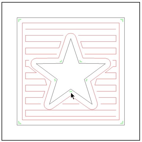
In the below example, the s-sweep pattern was used, the main tool was set to the.060 engrave and the fine tool was selected using a .005 engraver as the tool. Notice that there are far less tool path lines for the larger .060 engraving tool (in red) and the fine tool paths 9in green) are only in the interior corners of the star as well as in the corners of the square. Less tool paths will make for much faster processing time.
In this example, the main tool was set back to the .015 engraver and a gap of -0.020 inches was used. Notice how close the red colored tool paths are to the original black object lines?
If the Show Line Style is turned on, you can see how the star is now slightly smaller and a little distorted. This may or may not be desirable, depending on how you want the objects to look.

As stated before, users should experiment to determine which fill style and settings are best for their particular applications.