As an alternative to engraving or routing out text or graphics in a material, it may be desirable to leave the text or graphics un-engraved, but engrave or rout out the area surrounding them. An example of a routed out background is shown here.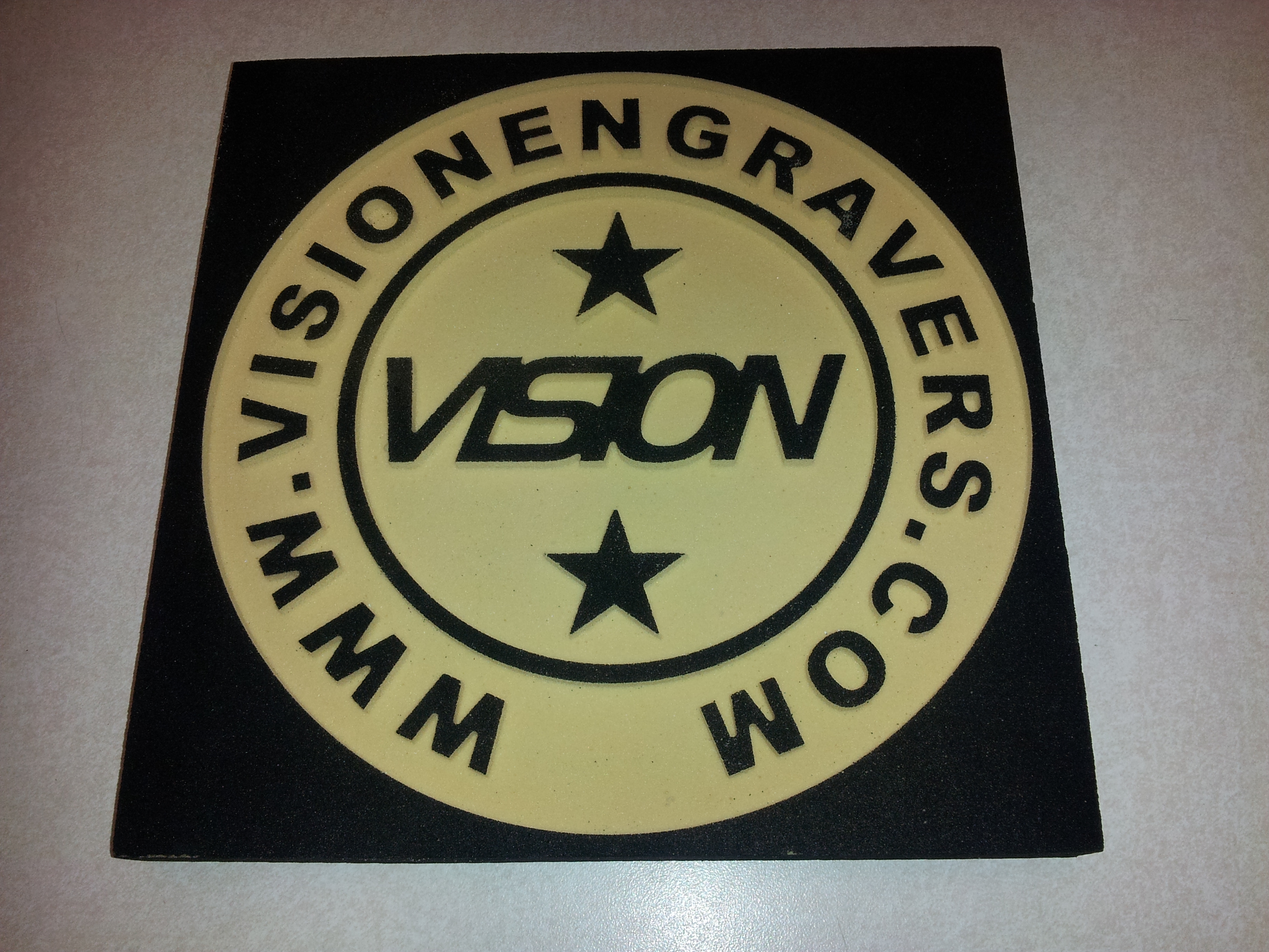
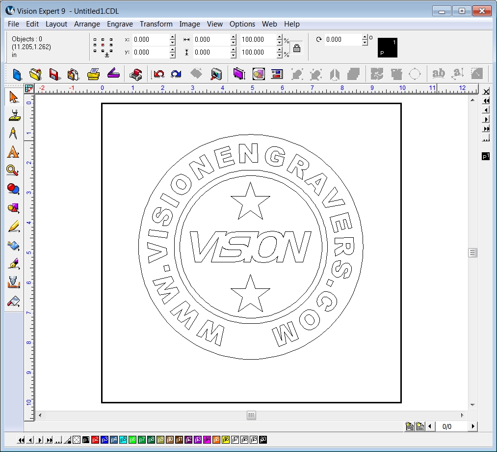
In the above example, three circles were drawn in the Vision engraving and routing software to set the outside boundary and to locate an un-engraved circle around the two stars and the Vision logo. Starting with these three circles, the graphic is shown below.

The Vision logo and two stars were added.
![]()
The Vision website information was added by placing text on a path, using the middle circle.
The text was converted to graphics in order to allow the software to “make a path” with it.
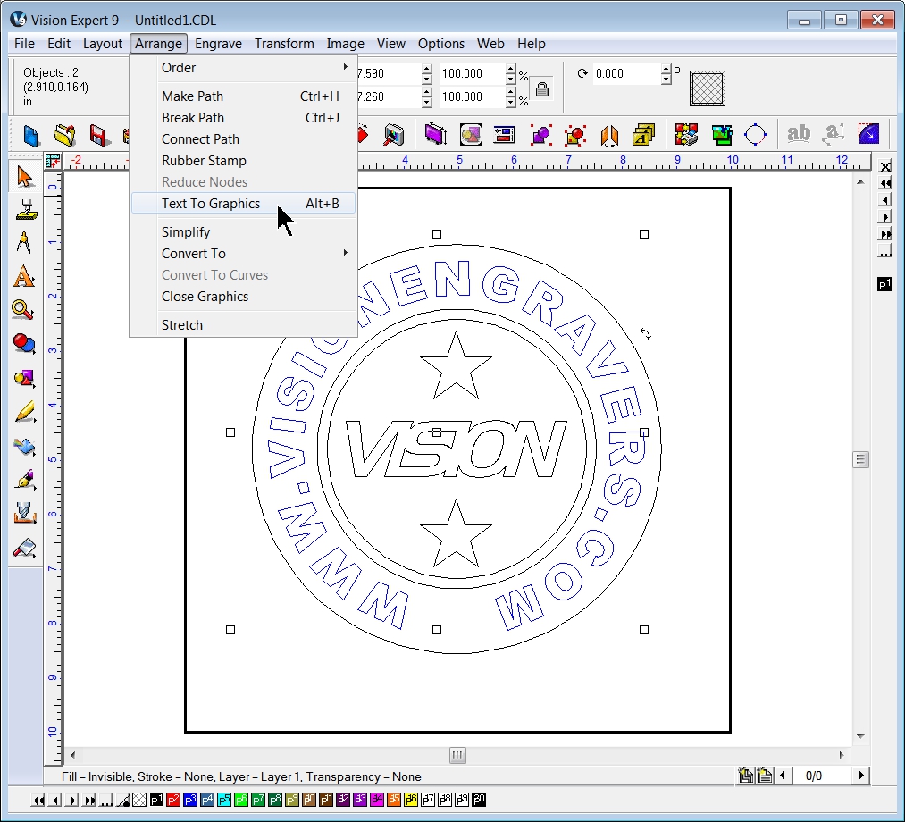
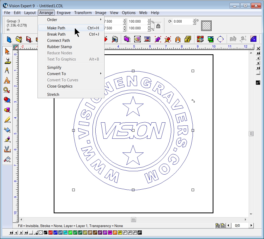
All objects were selected and the Make Path function was used. The Vision engraving and routing software automatically converts the image into one where a fill can be applied to open areas. This is an automatic function and is very accurate at determining which areas should be engraved and which areas should not.
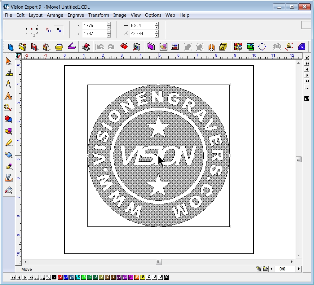
Once the path is made, the user can click and hold down the left mouse button when the cursor is over the node in the middle of the selected objects, which will display the areas the Vision software has determined to be “filled”, or which areas can have a tool path applied. The area is represented by the gray area as shown below.
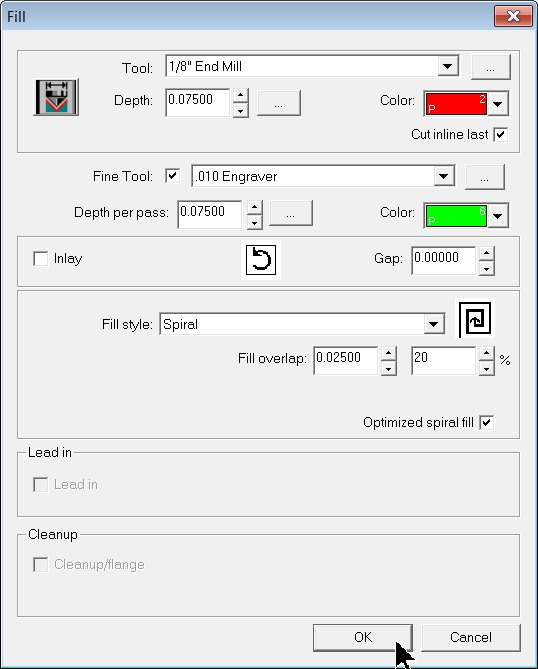
A fill can then be applied using the Fill tool (Vision Expert and Vision Pro use the Fill tool in the Tool Path Tools menu as shown).

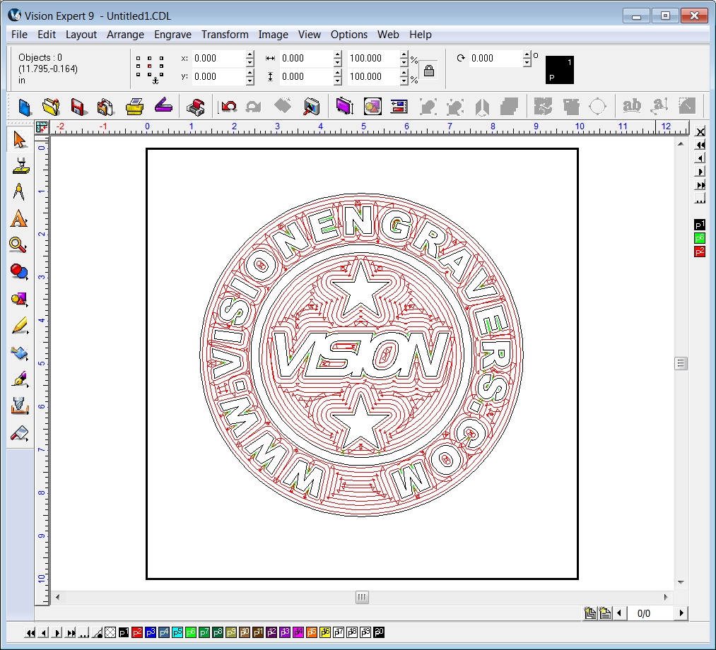
In this example, a 1/8th inch End Mill was chosen for the primary Tool in the color red and a 0.010 Engraver was selected as the Fine Tool in the color green. The material used was Sign Foam, so the depth was fairly deep – set to 0.075 inches – and engraved in one pass. The Spiral Fill style was used to shorten the routing time. A 20% overlap was used and the Optimize spiral fill option was selected.
After selecting OK, the final fill pattern is shown below. Note that the red tool path will normally be engraved before the fine tool path in green.
Note that with large engraved areas such as this, it is best to use the Set Surface function and not the Proximity Sensor. If the Proximity Sensor is used, the nose cone may “fall” into an engraved area and cause the background to be engraved at different depths. Using Set Surface and letting the tool path depth setting dictate how far the tool will go into the material prevents the possibility of having uneven engraving depths.