In this tutorial, multiple parts will be serialized and cut out of a sheet of material.
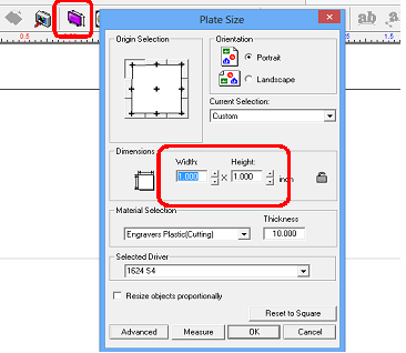
Begin by setting the plate size to the desired finished size of the part. In this example, the Width and Height were set to 1.00 inches.
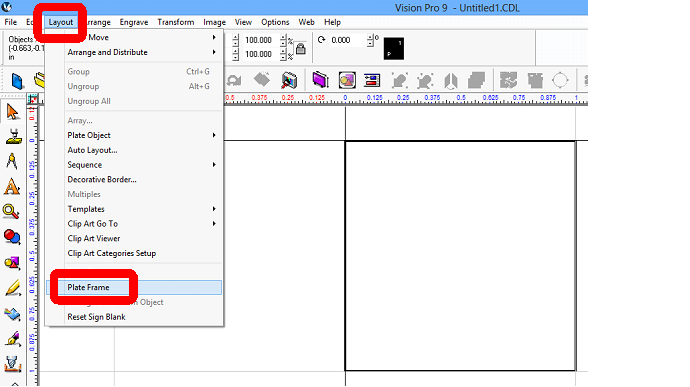
On the top menu bar, select Layout, then select Plate Frame.
In order to cut the part out, a Male Tool Path was applied to the plate frame. In this example a 1/8” End Mill was used to create the tool path.

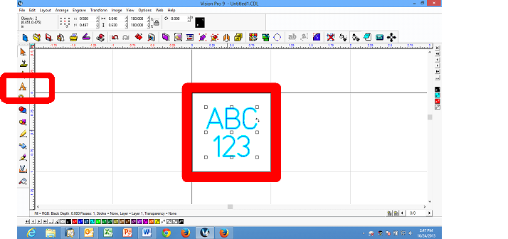
Use the Frame Text Compose Tool and type in “ABC”, then press the Enter key and type “123” to produce two lines of text as shown. Create a tool path for the text using the Online Tool Path Tool. A .015 Engraver was chosen as the tool in this example.
Select the Multiples icon on the top toolbar.
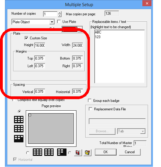
The Multiple Setup window will appear. For Plate, enter the size of your material in the Plate size text entry boxes. In this example, a 24 x 16 inch sheet of material was used. Adjust the Margins and Vertical/Horizontal Spacing to allow for the tool path and kerf produced by the tool. For this example, 0.375 inches was used in these areas.
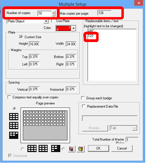
Enter the Number of Copies to be produced in the text entry box. As you enter numbers, note that the Page preview at the bottom of this window displays a layout of the parts.
To start serialization, select the text you wish to serialize in the Replaceable items/text field, then select OK at the bottom of this window.
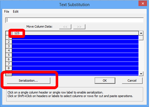
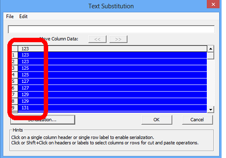
The Text Substitution window will appear. Select the column header (where 123 is shown), which will highlight the entire column, then select Serialization…
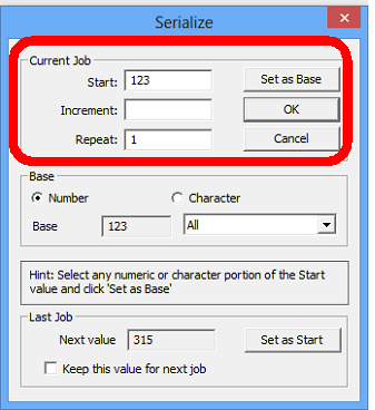
The Serialize window will open. This window allows the user to set the base number, the increment of the serial numbers and number of each serial produced.
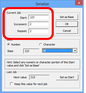
In the below picture, the starting serial number is 123 and the increment and repeat values are set to 2. This will produce serial numbers of 123, 123, 125, 125, 127, 127, etc. Select OK to finish creating the serial number list.
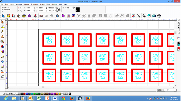
The list of serial numbers should appear as below.
Select OK to accept this list of numbers and create the layout of parts in the Vision 9 software.
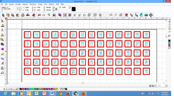
The job can now be sent to the machine.